
The Nuts and Bolts of Nuts and Bolts
Deploying AN Bolts, AN960 Washers and Lock Nuts on Structural Joints

This is a bolted corner of a Sonex Onex airframe.
The focus of this article is on AN bolt length selection, washer usage and nut installation for structural joints. It is based on a series of columns I wrote for KITPLANES Magazine. Those columns were inspired by the almost daily questions I received on hardware in my former role as Sonex Tech Support Guy. In covering this topic my goal is to give you the knowledge—and the permission—to choose the proper length bolt regardless of what a kit’s assembly documentation calls for. If you need to pour yourself a drink before we begin, I understand. I did.
Both AC43.13 and The Standard Aircraft Handbook, which draws heavily from AC43.13 should be in every homebuilder’s toolkit.
The guidance I’m sharing here is gleaned from a decade’s-old resource available to every homebuilder, Advisory Circular 43.13-1B, Acceptable Methods, Techniques, and Practices—Aircraft Inspection and Repair. AC 43.13 defines best practices for aircraft construction, maintenance and repair. It is a must-have for every homebuilder and homebuilt owner. I also reference the Standard Aircraft Handbook, which should be on every homebuilders workbench. It draws heavily from AC43.13.
I’m presenting the accepted methods in my own way, from my experience as a homebuilder and my experience supporting homebuilders. If one is willing to take a deep a dive into AC43.13 you’ll find a few contradictions and some statements that don’t hold up to scrutiny. AC43.13 was written decades ago and though adopted as the standard—at least the standard for non-pressurized Standard category aircraft—, I’m not sure it has ever undergone a comprehensive review.
Shear Loads on Fasteners
Nearly every fastener in an airframe is loaded in shear. That means the loads the fastener experiences are trying to tear through it like a wire cutter through a wire. As such, the diameter of a fastener is selected to endure the expected shear loads, plus a significant margin of safety. That requires engineering calculations. While my goal is to give you the knowledge to choose the correct length bolt regardless of what kit documentation calls for, I caution you to not change a bolt’s diameter without consulting the kit’s manufacturer. Oversizing a hole to accommodate a larger diameter bolt can diminish edge distance, weakening an assembly. Bigger isn't necessarily better.

These illustrations show the shear loads acting on a fastener. A fastener’s diameter is determined by the loads it must endure.
Now that we’ve established that the diameter of a fastener is determined by the shear loads it will experience, and that that is best left to the airframe’s designer, the length of a bolt is determined solely by the total thickness of the parts being fastened. That requires only eyesight, not an engineering degree.
The Parts of A Bolt
The smooth shaft of the bolt—the grip—is the portion of the bolt meant to carry the shear loads. The grip must extend fully, if just barely, through the parts being fastened. As bolts grew longer, it is the grip that grows longer to accommodate thicker parts and assemblies. The threaded portion remains constant, within manufacturing tolerances, which we’ll get to later.
These key areas of an AN bolt impact its installation.
There is a transition area between the grip and the threads, it’s called the relief, but I think transition is more descriptive. I consider this a no-man’s-land. It’s too narrow to be within the parts being fastened, and a nut installed that near the grip may not tighten properly before it bottoms out. The transition should always be bridged by a washer.
AN Bolt Diameter and Length Identification
A bolt’s call-out—AN3-21, AN5-23, AN4-7, etc.— defines its diameter and length. The first number following the prefix “AN” is the bolt’s diameter expressed in sixteenths of an inch. A -3 bolt is 3/16-inch diameter. A dash -4 bolt is 4/16-inch (1/4-inch) diameter, and so forth. That’s pretty straight forward.
The second number—the number following the dash—is the bolt’s length. That value is inconstant across the various diameters. An AN3-31 bolt has nominal grip length of 2-3/4-inches. An AN6-31 has a nominal grip length of 2-9/16-inches. AN4-31 and AN5-31 bolts have a nominal grip length of 2-11/16-inches. But none of that matters to us. You could mix bolts of every length in a coffee can and still achieve proper bolt length selection without knowing if you installed an AN3-7 or an AN3-10 in a particular hole. All you need is your eyes.

By simply observing how much grip sticks through a hole, you can chose the correct bolt length every time.
Above are three consecutively longer AN3 bolts. The one on the left is too short, its grip is within the parts being fastened. The one in the middle is correct, its grip extends fully through the parts. A washer will prevent the nut from bottoming out on the grip. The bolt on the right is too long and would require too many washers. A longer bolt doesn’t add strength so there’s no point in using a bolt that is longer than necessary.
A short bolt, however, can add weakness, as shown below. The threads of a bolt are stress risers; weak spots where a crack or break is most likely to occur as shear loads build. The threads of a bolt aren’t meant to carry shear loads and must never be inside the parts being fastened.

This bolt broke at the threads, which are not intended to carry shear loads.
Selecting Grip Length
Section 3, Bolts, of Advisory Circular 43.13-1B, states: “In general, bolt grip length of a fastener is the thickness of the material the fastener is designed to hold when two or more parts are being assembled. Bolts of slightly greater grip length may be used, provided washers are placed under the nut or bolt head. The maximum combined height of washers that should be used is 1/8 inch. This limits the use of washers necessary to compensate for grip, up to the next standard grip size.”
While AC 43.13 implies a maximum of two AN960 washers may be used, it is widely accepted that up to three washers can be used on a bolt installation, though the third is often an AN960L thin washer. The reason will be discussed later.
I’ll point out that the total thickness of the materials being fastened will almost never conform to the polite system of AN bolt grip-length progression. There are an infinite number of total material thicknesses possible and a finite number of available bolt lengths. For that reason, and to bridge a bolt’s transition, plan on having a washer under every nut.

Note the lack of bolt length call-outs in the Pietenpol Sky Scout plans.
In the days of yore (your dad, your grandpa, your great-grandpa), bolt length was often absent from airplane plans, like these Pietenpol Skyscout plans. To today’s builders these plans may seem to lack detail, but everything needed is there; namely, the diameter of the bolt. The bolt’s length, washer usage and nut type are dictated by best practices. Back in the day, it was assumed best practices would lead each builder to the correct grip length. But things changed.

In the late 1970s, Frank Christensen introduced the Christen Eagle II with the promise the kit included everything needed to complete the airplane. That included fasteners and the detailed documentation to deploy those fasteners about the airframe. I don’t know how well that worked for individual Eagle II builder’s, but I know from my years at Sonex that the very specific hardware call-outs in the Sonex airframe plans cause far too many builders anxiety when a bolt call-out is too short or too long for their particular assembly.
Builder’s hesitate to substitute a bolt length when what the plans call-out is too long or too short. You may wonder why assembly documentation would call for the wrong length bolt. Beyond occasional human error, the most likely cause is a thing called tolerance stacking.
Tolerances and Tolerance Stacking
Every raw material and piece of hardware you use on your homebuilt has a manufacturing tolerance. Tolerance stacking, loosely defined, is the impact the acceptable tolerance range of each part has on the total thickness of the stack of parts being fastened.
The grip lengths of AN bolts have a manufacturing tolerance of plus or minus 1/64-inch. That means two AN bolts of the same nominal length could have comparative grip lengths that differ by 1/32-inch. That 1/32-inch length difference means little to a 3-inch long AN3-33 bolt, but becomes significant to the total length of an AN3-3 bolt, whose nominal grip length is only 1/16-inch to begin. You could have one AN3-3 bolt with an effective grip length of 1/32-inch and one with an effective grip length of 3/32-inch.
The following series of photos depicts the variations that exist in AN hardware, underscoring why plans can sometimes be wrong when calling for very specific hardware installations.

In this photo you can see that these randomly chosen sequentially longer bolts do not have a linear increase in grip length, as you would expect. The reason is manufacturing tolerances. That is why a specific bolt length called for in assembly documentation can be too long or too short for your particular assembly. Manufacturing tolerances negate the perfect world depicted in assembly documentation.
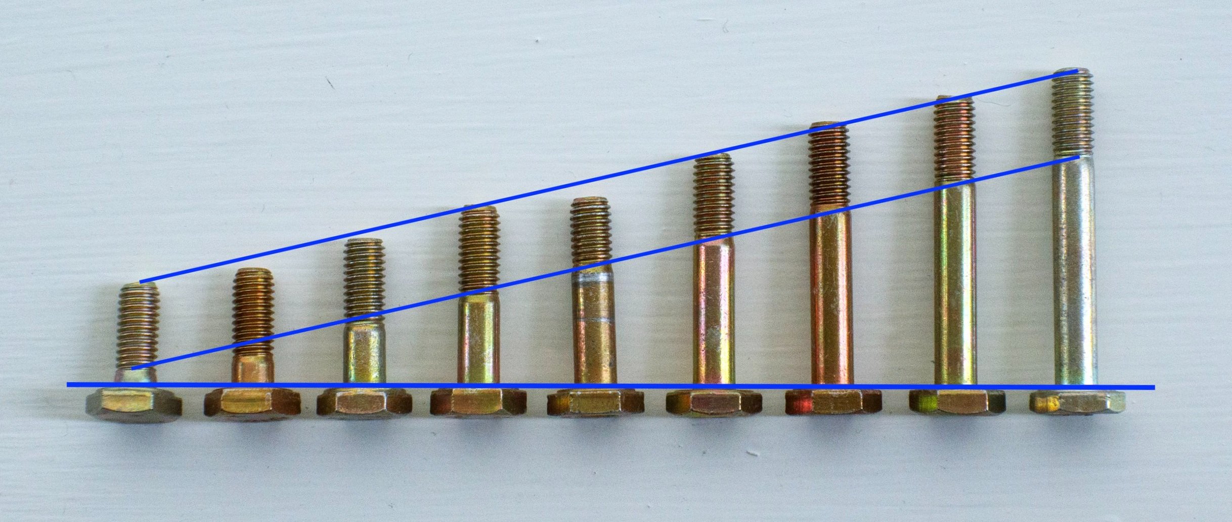
The over-all length of a bolt also has a tolerance. If you take another look at these AN3 bolts arranged sequentially by length you’ll see their over-all length is also non-linear. Though you’d expect a linear increase in grip length and a stable threaded length, that is not the case.

Here the ends of the bolts are lined up to better show that the threads of bolts vary within the accepted tolerance, yet remain the same length as bolts grow longer. Each nominal increase in bolt length is an increase in the grip length, the nominal thread length remains constant.

This photo shows five AN3-10 bolts with the contact surfaces of their hex heads lined up. While grip length of these five bolts is relatively consistent, the middle bolt has a much longer threaded length. That impacts the number of threads exposed after a nut is installed. The generally accepted number of threads left protruding after a nut is torqued is one to three, but this illustrates why it can be more.

When this photo ran in KITPLANES a reader commented that too many threads were showing for the installation to be acceptable. Where the reader worked, no more than three threads could be exposed beyond the nut. The reason, he said, was that if three threads were showing, the nut was bottoming out on the fastener’s shank. I’ve shown that the threaded length can vary from bolt to bolt. While you must never accept less than one thread protruding from the nut, manufacturing tolerances may leave you with more than three threads from time to time. That’s fine, as long as the nut is torqued properly and not bottomed out on the bolt’s grip.
As was demonstrated earlier, a bolt’s grip length doesn’t need to be defined by an airplane’s designer. Choosing the correct grip length is one of the easiest things a homebuilder can do and requires only eyeballs, not engineering. While I was on a homebuilt-judging ride-along during AirVenture 2023 a short bolt was pointed out to an aircraft owner and the owner responded that that was what the plans called for. That doesn’t make it right, and I’ve demonstrated why the plans and the real-world can disagree on the proper bolt length.
Everything above was a wordy preamble to these simple steps for choosing the correct length bolt or screw.
Make sure all the correct parts are in all the correct places.
Make sure the parts—both the edges and the holes—are deburred. Burrs are not only poor workmanship and stress risers, they impact how well parts nestle together, which can impact the length of the bolt.
Decide if you are placing a washer under the head of the bolt. I almost never do. We’ll cover washer usage shortly.
Select the shortest bolt whose grip extends at least minimally through the parts being fastened. Sometimes it will barely poke though, sometimes it will poke through nearly 1/8-inch. The left bolt has no grip extending beyond the parts, the right bolt has more than necessary. The middle is just right.

Eyeballs. That’s all that’s needed to select the proper length bolt.
Washers
Washer usage is an often contentious topic. But then, since the birth of social media, what isn’t? When I worked at Sonex, not a week (sometimes, a day) went by that I wasn’t asked about washer usage on threaded fasteners. Often a debate and sometimes an argument ensued. Here, I’ll focus on why washers are used on threaded fasteners. As my middle-school math teach once said, “Your homework is due on Monday.” He also said, “If you know the why, you know the how.” The second quote is more befitting the goal of this webinar.

This shows poor washer usage. Not only does ir not match match the plans, it doesn’t meet best practices. There should never be two washers under a bolt head and I’’d argue that there seldom needs to be one.
My focus is on the use of AN 960 washers with structural fasteners in non-rotating assemblies. In other words, when securing Part A to Part B. In these instances AN 960 washers don’t contribute strength to the joint, they facilitate the correct nut position on the threads of bolt (which, I suppose, does contribute strength to the joint).

There are two types of AN 960 washers. The most common version (left) is 1/16-inch thick. A derivative, the AN960L washer, is 1/32-inch thick—half the thickness of the common AN960.
AC 43.13-1B states: “Plain washers are widely used with hex nuts to provide a smooth bearing surface, act as a shim to obtain the proper grip length… and to position castellated nuts in relation to drilled cotter pin holes in bolts.” It may be semantics, but I disagree with the statement “Plain washers…act as a shim to obtain the proper grip length.” Proper grip length is determined by the thickness of the parts being fastened. Washers act as shims to prevent the nut from bottoming out on the grip of the fastener.
AC 43.13 also says up to two AN960 washers can be used on a fastener installation, implying a maximum of 1/8-inch total thickness of washers. If more than 1/8-inch of washers is needed, you may need a shorter grip-length fastener.
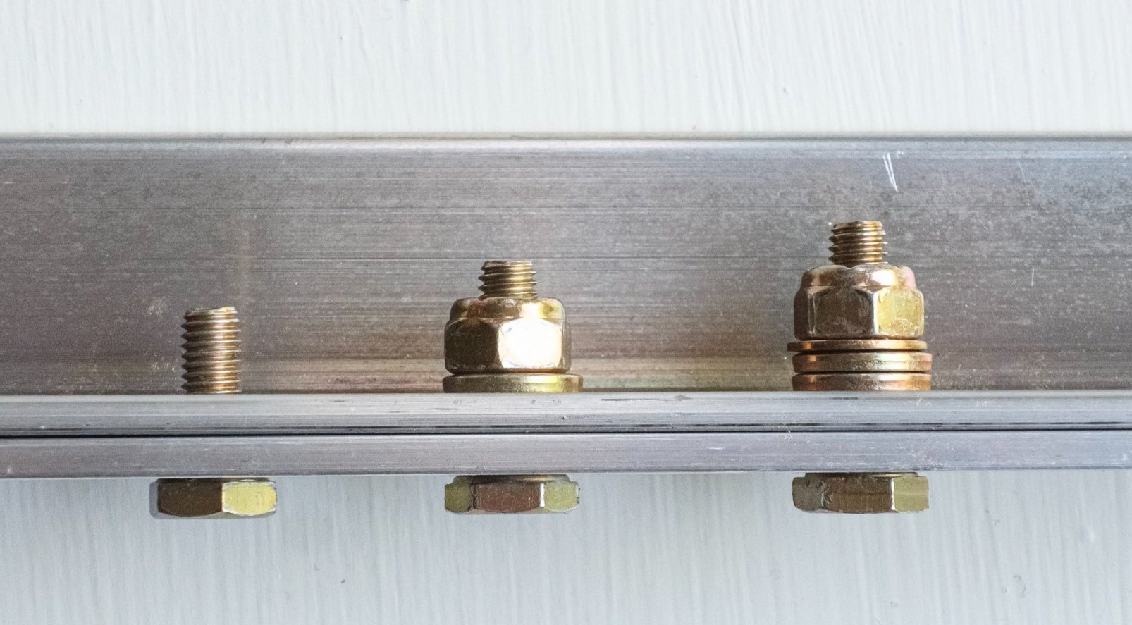
The bolt on the left is too short—no grip protrudes through the parts being fastened. The center bolt is ideal with only one washer under the nut. The right bolt is too long though on rare occasions you may find two full washers and one thin are needed. The most likely cause for this is tolerance stacking.
AC 43.13 recommends that cadmium-plated steel washers be used under nuts and bolt heads on aluminum and magnesium surfaces to prevent corrosion. It doesn’t say whether they are referring to cadmium-plated nuts and bolts, which is the focus of this webinar, or unplated nuts and bolts. To me, this directive doesn’t hold up under scrutiny. The hardware is already cadmium plated, and flush and washerhead screws are installed without washers though they are made of the same steel and contact aluminum surfaces. What’s more, the grip of the fastener is in direct contact with the same aluminum or magnesium surfaces. If there will be corrosion it will still occur on the most critical part of the bolt, the grip.
Supporting my assertion that washers are not required under the head of a bolt, flush screws and AN525 washer-head screws are always installed without washers under their heads.

Corrosion should only be a concern on airframes that have been put out to pasture, dug out of hangar after years of neglect, or whose construction and care have been so grossly ignored the airplane shouldn’t be flying anyway.
My 1991 edition of the Standard Aircraft Handbook states “The AN960 washer is used under hex nuts,…” and goes on to repeat, almost verbatim, the text from AC 43.13. Two pages later, however, it contradicts itself with the statement “Be sure that washers are used under heads of bolts and nuts unless their omission is specified.” It doesn’t say why, leaving us to argue amongst ourselves. And so we do. But I think I know why that line is included. The Standard Aircraft Handbook is adapted from AC43.13, which was written for, as its name implies, standard category aircraft.
The front page of AC43.13 carries, in part, this statement:
“This advisory circular contains methods, techniques, and practices acceptable to the (FAA) Administrator for the inspection and repair of non-pressurized areas of civil aircraft, only when there are no manufacturer repair or maintenance instructions.”
It goes on to say the information the information can be used if “…it is not contrary to manufacturer’s data.”
AC43.13 was written for aircraft with a Standard Airworthiness certificate. Therefore, if an aircraft was licensed with a washer under the head of bolt it must remain there even if an otherwise airworthy bolt installation can be achieve without one. I mentioned earlier how individual company’s may have their own standards, and one such standard may include always placing a washer under the head of a bolt.
While writing this I had the owner of an aircraft repair facility tell me that the rules they were taught in A&P school went out the window the first time he worked on a particular brand of Standard category aircraft, which had its own way of doing things.

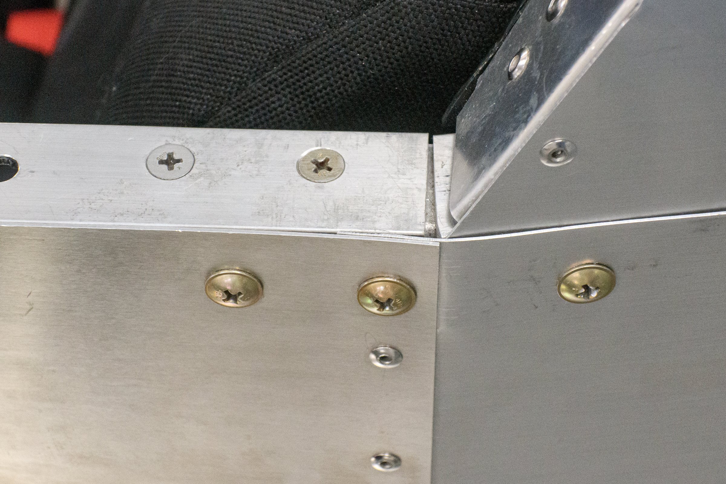
I explored the hangars of an aircraft repair facility to see how everything from Cubs to Cessnas to Cirruses are assembled. For the majority, washers were absent from under bolt heads. This Cessna seat track is installed without a washer under the head of the bolt.
Here are a few more reasons to avoid unneeded washers.
Installing unnecessary washers impacts an airframe’s empty weight and cost. If you adopt the personal policy of placing a washer under every bolt head a certain percentage of bolts will need to be lengthened to have the correct grip length, further compounding weight gain. That doesn’t impact a tube and fabric, fiberglass or wood airframe so much, but it can add up on aluminum airframes which, as shown here, can have many bolted joints.
Installing unneeded washers also encourages embedding loss.

The wear on the quarter to the left is similar to embedding loss, which is the erosion of a surface.
Embedding loss, simply put, is surface erosion. Grab a handful of change and you’ll see graphic evidence of surface erosion where the Lincoln Memorial has been rubbing against Monticello in pockets, cash register drawers and vending machines, possibly for decades. Similarly, the high spots of freshly minted washers rest on the high spots of neighboring washers, nuts and on the surfaces of the materials being fastened. Over time they erode, if ever so slightly, as do the mating surfaces of the fastened parts, creating space where there was no space. The more layers there are, the greater the potential for embedding loss. Embedding loss can cause a bolt to loosen even though the nut is positioned on the bolt’s threads exactly where it was when it was tightened.

AN 960 washers are not meant to distribute loads across soft materials, such as wood and fiberglass. That’s the job of AN 970 large area washers, as seen on this Fly Baby spar.

Both of these washers are for AN4 bolts but both serve different purpose. The one on the left is an AN960 washer—the focus of this article. the one on the right is the AN970 washer, often called a fender washer or a large area washer.
AN970 washers are much larger in diameter than AN960 washers and must never be omitted when called for in construction documentation. They do critical work beyond positioning a nut properly on the threads of a fastener. They spread loads across the surface of soft materials, such as this wood spar, to reduce embedding loss. An AN960 washer would quickly embed itself in the wood.
Washer usage begins by choosing a fastener with the correct grip length. If a nut can be installed without a washer and without bottoming out, the fastener’s grip length is too short. As mentioned earlier, best practices dictate the grip must extend fully (if only barely) through the parts being fastened. At least one washer is needed under the nut to keep it from bottoming out on the grip of the fastener.

The need for a single AN 960 washer (an AN 960L thin washer was not quite thick enough) makes the center bolt in this photo the perfect length. The right bolt is longer than necessary, as three washers were required to prevent the nut from bottoming out on the bolt’s grip.
Here’s how I deploy washers:
To keep weight down, chose the shortest fastener possible with no washer under the fastener’s head.
When possible, I use an AN 960L thin washer instead of an AN 960 washer under the nut. Thin washers are half the thickness and half the weight of the standard AN960 washer.
If the fastener’s’s grip length requires two washers, I place the second washer, a thin washer if possible, under the nut. The use of an AN 960 and an AN 960L (thin) washer in this assembly tells me the builder was weight conscious. It would have been easy, and correct, to use two AN 960 washers.
If a third washer is needed (a thin washer if possible, resulting in two standard washers and one thin washer) I first make sure I used the correct length fastener. Though using more than 1/8-inch total thickness of washers goes against best practices, sometimes the real world leaves us with no choice.
A fourth washer will never be needed. Instead, I reach for a shorter bolt
Washer usage is something each builder should be able to determine for themselves, regardless of what is shown in a kit’s construction documentation. Ask yourself, “What does this washer do? What does it add to the fastener installation?” The primary answer is AN960 washers position a nut correctly on the fastener’s threads. Best practices dictate the nut must neither bottom out on the fastener’s grip nor leave less than one thread of the fastener showing.
Ahhh, Nuts
Finally, we get to nuts. During my two decades in homebuilding I dealt with my share of nuts. Specifically, self locking nuts (aka stop nuts) on the bolts of permanent, non-rotating assemblies. That is the focus of this section.
Unlike common nuts, which can be spun fully onto a threaded fastener by hand, self-locking nuts have high friction drag when their locking mechanism contacts the threads of a bolt. The two most common self-locking nuts, shown below, are elastic stop nuts and all-metal stop nuts.
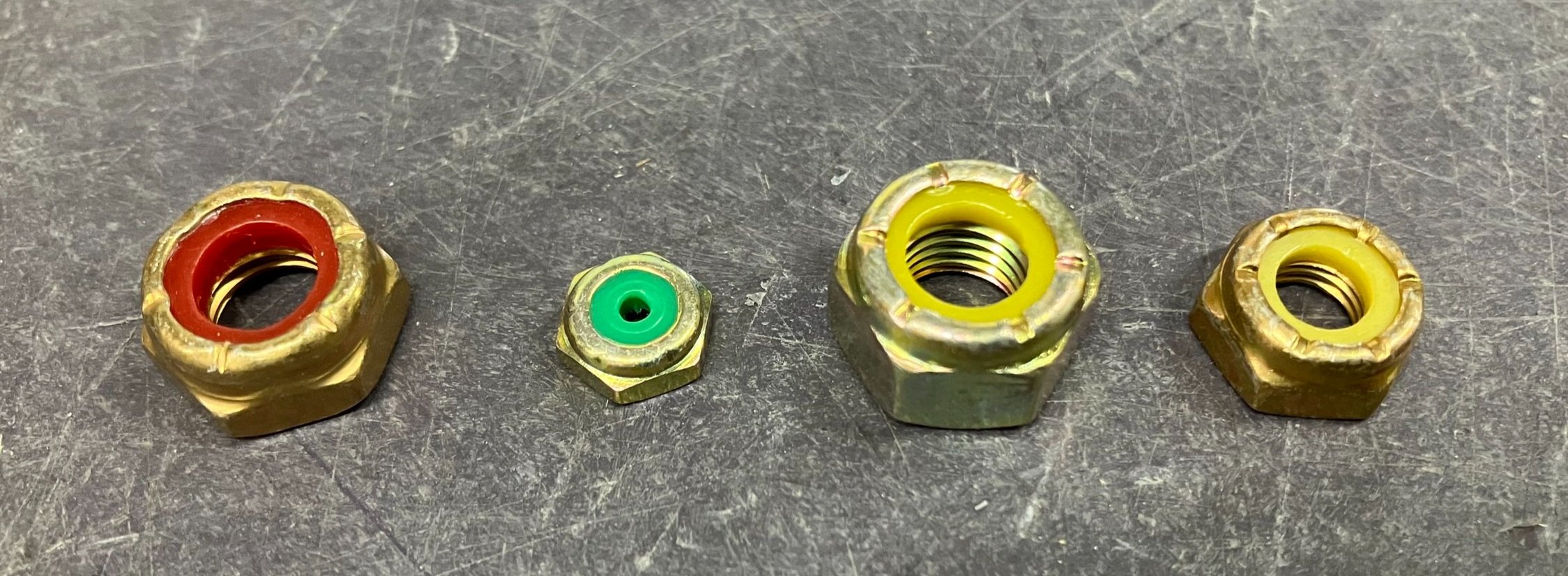
Here is a variety of elastic stop nut. The elastic—often nylon—material grips the threads of a fastener.

These all-metal stop nuts use the friction of deformed threads to hold tightly to a threaded fastener.
All-metal stop nuts are required where temperatures exceed 250=degrees F. This requirement applies when it can be reasonably assumed the nut will experience those temperatures, but it does not mean elastic stop nuts can’t be used under the cowl, though some balk at the sight of an elastic stop nut under a cowl.

This elastic stop nut is securing a motormount to an airframe. Though it is under the cowl, it should never see temperatures anywhere near 250-degrees. More troubling to me is that someone used that bolt as a ground point, leaving minimal thread protrusion beyond the nut. An alternate ground point should have been found.

These all-metal stop nuts were under the cowl of a Cessna. I’ve noticed Standard Category aircraft seem to employ more metal stop nuts throughout an airframe than EA-B aircraft do, though that is a casual observation.
All stop nuts share the characteristic of having a high-friction grip on the fastener. However, elastic stop nuts, in particular, loose some of their grip each time they are used. It is generally accepted that a lock nut can be reused once. If you are servicing an airplane you may not know if a nut you remove has already been reused. Always reach for a new one. However, to save money and resources, when putting something together temporarily use a used nut and bolt for the initial assembly and replace them with new on final assembly. There’s no point in compromising new hardware for a temporary need.
Installing Nuts
Installing a nut begins, of course, by installing the proper length bolt. But even the physical act of installing a bolt needs a brief mention. Avoid twisting or “screwing” a bolt into its hole. Doing so can cause scoring of the bolt’s shank, weakening its strength and exposing the underlying alloy to a greater risk of corroding. I’d never allow this on my airplane. If you encounter resistance inserting a bolt with your thumb, tap it in with a rubber mallet. That reduces the risk of scoring the grip and also eliminates an oft-cited reason for placing a washer under the head of a bolt, which is to keep the rotating bolt head and tool from damaging the surface of the airframe. Damaging the grip of a bolt can be avoided—without adding a washer—by holding the bolt still and turning the nut. Both AC43.13 and I agree turning (“tightening”) the nut while holding the bolt is the proper method for securing hardware.
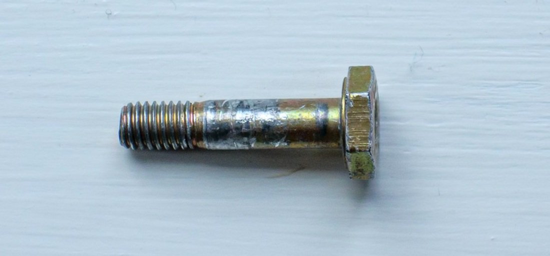
This bolt was “screwed” into its hole, which damaged the grip and stripped away the cadmium plating that protects the grip from corrosion.

The score marks around these bolt heads were caused by rotating the bolt with socket wrench. Such damage can be avoided by rotating the nut, not the bolt.

The inevitable washer under a nut prevents a rotating tool from contacting the airframe’s surface while the nut is tightened, protecting that surface of the airframe.
Torquing Nuts
Torquing nuts can be debated for hours without consensus. AC43.13-1B recommends torquing every nut. I torqued very few nuts. I snug them by feel, as was taught to me by trusted old-timers. When I spot-check my results with a torque wrench I’m spot-on enough to forgo the torque wrench in all but the most critical applications. I’ve seen builders rely on torque wrenches to their detriment. Used improperly, they can provide a false sense of accuracy. If you do use a torque wrench, there is more to it than waiting for the break-away “click” or watching the pointer on a beam-type torque wrench.
To begin, torque wrenches must be calibrated at least once a year and after they are used as a hammer. There is no point in torquing to a very specific value setting if you aren’t actually achieving that value.

This beam-type torque wrench reads nearly 40 inch-pounds sitting on the bench. Clearly it needs calibration.

The break-away or “click”-type torque wrench bears a label certifying when last it was calibrated and when next it must be calibrated. The label is meaningless, however, if the wrench has been dropped or abused or if it is used incorrectly.
Other points to consider:
There are different torque values for fine- and coarse-thread fasteners.

Don’t confuse inch-pounds with foot-pounds.
Torque table’s reference a bolt’s grip diameter, not the size of the socket used to tighten the nut.
If you add an extension to the torque wrench (a crows foot adapter for instance, or a handle extension), the torque value setting goes out the window and algebra must be deployed to compensate for the change in the tool’s effective length.

Changing the effective length of a torque wrench changes the torque value.
The torque wrench must be pulled or pushed smoothly until the final torque value is reached; jerking the tool can over or under-torque the bolt.
The threads of the bolt and nut must be clean and dry. Lubricants, sealants and locking agents will reduce friction, resulting in an improper final torque value.
If the nut goes from turning with moderate resistance to stopping outright, the nut has bottomed out on the bolt’s grip. The resistance felt while torquing a nut should increase gradually as you near the required value, not come all at once.
Finally, the nut’s friction drag must be factored in. I’ll get to that shortly.

Using a beam-type torque wrench can range from cumbersome to impossible for many airframe bolts. If the nut in this photo had been inside the structure, instead of on top, it would limit the torque wrench’s range of motion and make reading the scale impossible. If the bolt head were up, torquing the bolt head could score the fastener, something we try to avoid, and the friction of the bolt turning inside the materials being fastened adds friction drag over and above the friction drag of the stop nut.
Friction Drag
Friction drag is the amount of effort needed to turn a stop nut on the threads of fastener. It is the friction between the stop material and the threads of the fastener. To achieve the correct final torque value, the friction drag of the nut must be measured and added to the bolt’s specified torque value. For example, if a bolt has a torque value of 50 inch-pounds and the nut has 10 inch-pounds of friction drag, the final torque value must be 60 inch-pounds. The first 10 inch-pounds of effort are serving only to turn the nut. If friction drag isn’t added to the final torque value, every bolt will be under-torqued.
One last wrinkle: A used self-locking nut will have less drag than a new one. If you are mixing new and used nuts in an assembly you need to keep this in mind. It’s another reason to always install a new stop nut.
Summary and Judgement
There will be some who counter what I’ve written with “well, I’m an A&P and…” Or, “At Big Box Aircraft we…..” The debates on washer usage and torquing, in particular, will go on forever though, in fact, they was settled decades ago with the publication of AC43.13 and the Standard Aircraft Mechanics Handbook, which draws heavily from AC43.13. As I pointed out, I disagree with AC43.13’s mention that a washer should be placed under a bolt head to protect against corrosion. I disagree, however, only after thoughtful analysis of the realities of that statement. Sometimes rules and guidance exist whose reason for being are unknown even to those who must follow or enforce them. Case in point:
I asked a former Air Force air traffic controller why aircraft on Air Force bases must get ATC’s permission to start their engines, as I did when I visited Minot Air Force Base. His response, “Because that’s how it’s always been done.” If you work for an aircraft manufacturer who dictates a washer under the head of each bolt, that is a rule you must follow. However, you don’t have to carry that over to your homebuilt aircraft or dictate that others must follow that guidance on their project.

Boeing may have its own in-house guidelines for hardware installations. Those don’t have to transfer to our Experimental Amateur Built sandbox.
I encourage everyone to get their own copy of AC43.13, which can be downloaded free as a PDF from numerous online sources and a copy of the Standard Aircraft Handbook to keep on or near their workbench. Both are chock full of indispensable guidance for every homebuilder.
You should never need to be stalled waiting for a kit manufacture to give you permission to substitute a fastener’s length, or add or delete a washer. You should never have to question why the construction documentation has the wrong bolt length call-out.
If you know the why, you know how.
